Simple 1 watt to 12 watt
SMPS LED Driver Circuit
By: Alok kumar
Today we are going to learn to make a very simple
120V/220V smps LED driver circuit
which can be used for driving high
watt LEDs rated anywhere between 1 watt to 12 watts directly from any
domestic AC mains outlet.
The presented smps (switch mode power supply) LED driver
circuit is extremely versatile and specifically suited for driving high watt LEDs, however being a non- isolated topology does not provide safety from electric shocks at the LED side of the circuit.
Apart from the above drawback, the
circuit is flawless and is virtually
protected from most possible mains
surge related dangers.
Although a non-isolated
configuration may look a bit
undesirable, it relieves the
constructor from winding complex
primary/secondary sections on E-
cores, since the transformer here is
replaced with a couple of simple
ferrite drum type of chokes.
The main component here is IC which is. responsible for the main execution of all
the features is the IC VIPer22A from
ST microelectronics
, which has beenspecifically designed for such small transformerless compact converter applications.

The circuit functioning of this 1 watt
to 12watt LED driver can be
understood as:
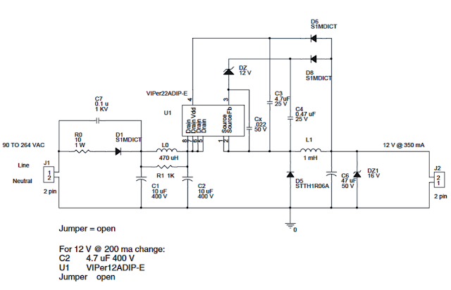
First the input mains 220V or 120V AC is half wave rectified by D1 and C1.
Posts Recommended:
D1 should be preferably replaced
with two diodes in series for
sustaining the 2kv spikes bursts
genareated by C1 and C2.
R10 ensures some level of surge
protection and acts like a fuse during catatrophic situations.
As can be seen in the above circuit
diagram, the voltage acroiss C2 is
aplied to the interal mosfet drain of
the IC at pin5 to pin8.
An inbuilt constant current source of the VIPer IC delivers a 1mA current to pin4 of the IC which is also the Vdd pin of the IC.
At about 14.5V at Vdd, the curent
sources gets switched OFF and
forces the IC circuitry into an
oscillatory mode or initiates pulsing of the IC to start functionibg.
The components Dz, C4 and D8
become the circuit regulation
network, where D8 charges C4 to the peak voltage in the freewheeling
period and when D5 is forward
biased.
During the above actions, the source or the referance voltage of the IC is set to
about 1V below ground.
For a comprehensive info about the
circuit details of the 1 watt to 12 watt
LED driver, please go through the pdf document presented by
ST microelectronics search it on google you will find it.
For any further querry please ask them in comment section.
Thank you
circuit is extremely versatile and specifically suited for driving high watt LEDs, however being a non- isolated topology does not provide safety from electric shocks at the LED side of the circuit.
, which has beenspecifically designed for such small transformerless compact converter applications.

understood as:

Posts Recommended:
- Make Automatic Emergency Light Circuit
- Simple 12 v 1 amp SMPS power supply, battery charger, LED driver circuit
- Make 5V 1Amp Cell Phone battery Charger Circuit from 220/110v
- Make 5V 150mA power supply using a IC-LR645
- Make Simple Light Dark Detector circuit using LDR
- Make 0~12V Variable Transformerless Power Supply, LED Driver, Electronic Dimmer
C1 along with the inductor L0 and C2 constitute a pie filter network for
cacelling EMI disturbenaces produced.
No comments:
Post a Comment